
Worm Drive Reading: Forward Motion and Self-Locking Conditions
2026-11-06
Worm Drive Reading: Forward Motion and Self-Locking Conditions
Worm Drive Reading requires keeping the direction of power transmission visible. A worm can drive its mating wheel, while the reverse attempt from the wheel toward the worm can encounter a different frictional relationship. Manufacturers describe self-locking in that reverse-driving context, with explicit design and operating conditions. The term should therefore be read as a qualified mechanism, rather than a universal promise attached to every right-angle reducer.
Identify the worm and its mating wheel
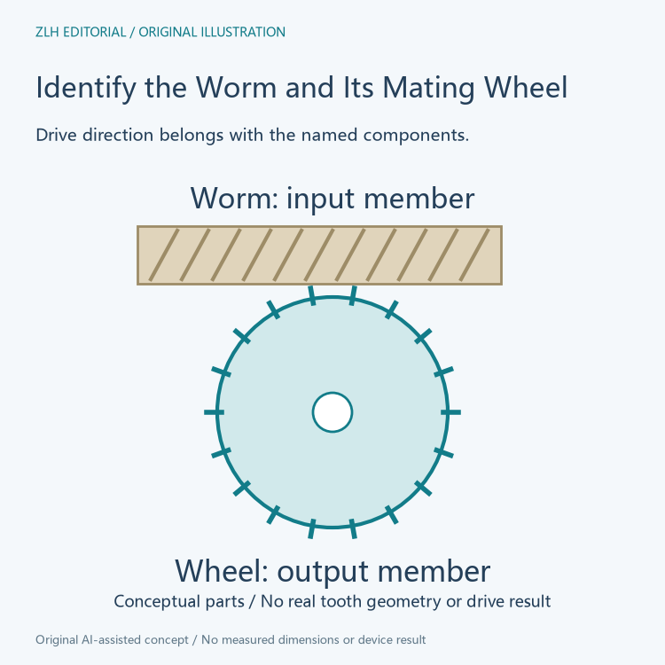
Bodine's official worm-gearing introduction describes a screw-like worm turning a wheel with the corresponding modified teeth. Its explanation connects this arrangement with a large reduction in limited space. Naming the two components helps distinguish the member that supplies the input from the wheel that receives the motion in the illustrated drive account.
A technical drawing can show these responsibilities without claiming that every gearbox with perpendicular shafts uses the same mechanism. Shaft orientation describes geometry, while worm and wheel identify the actual mating parts. A learning note should name the gearing type before applying a statement about friction or reverse transmission to it.
Reverse driving asks a different mechanical question
Bodine explains self-locking as a case where the worm drives the wheel but the wheel cannot back-drive the worm because of friction. This is a direction-dependent relationship. It concerns the input and output members rather than the direction of electrical current. It is different from saying that neither component moves, or that the motor has been electrically commanded to hold a position.
Tsubaki's official self-locking technical note defines the effect in its stationary worm-reducer context, where trying to turn the output does not start the input shaft. It also discusses a case requiring a large output-side force to turn the input. Its wording preserves a range of braking effects rather than making every resistance to reverse movement identical.
Friction and geometry remain part of the definition
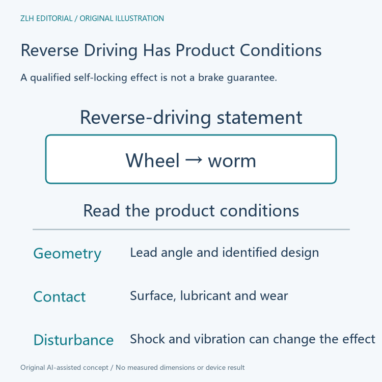
Tsubaki identifies worm lead angle, tooth-surface condition and lubricant as influences on the self-locking effect. Bodine likewise qualifies the ability by design and ratio, and says that wear reduces the effect. These statements explain why the label alone does not provide the full account of a particular reducer's reverse-driving behavior.
A contributor should keep the manufacturer's exact product and conditions beside a self-locking statement. The pages contain numerical ratio examples, but those numbers belong to their respective explanations and products. A value from one manufacturer's account should not silently become a general threshold used to classify every worm drive offered by another supplier.
Sliding contact helps explain the frictional context
Bodine distinguishes the sliding contact in its worm-gearing explanation from the predominantly rolling contact of its spur-gearing comparison. This provides a physical reason for considering friction, lubrication and wear alongside the gearing relationship. It is more informative than treating a reducer's ratio as the only property that matters.
The same article discusses modified enveloping forms that increase contact area. That is another construction description with its own context. A broad learning note can recognize that worm sets have different designs while avoiding an assumption that every design shares one fixed efficiency or identical frictional behavior. The identified product documentation remains necessary for numerical comparisons.
Static wording does not describe every disturbance
Tsubaki explicitly warns that shock or vibration can reduce the effectiveness of the self-locking effect. Bodine says that the effect should not serve as the application's primary braking mechanism. These are concrete limits on the term, rather than optional fine print to remove when shortening the manufacturer's account.
A useful equipment description can distinguish gearing construction, the stated reverse-driving tendency and any separately identified brake. A brake entry names another component and function. The presence of a worm gear does not establish that such a component exists, while the presence of a brake does not erase the need to identify the actual gear mechanism.
Use the mechanism as a reading framework
Both complete primary pages were read on November 6, 2026. Bodine's article is dated April 2016; its mechanism explanation is used here without presenting it as a new release. Tsubaki's numerical examples remain scoped to its stated reducer family. This article provides no load-retention design, test procedure or recommended gearbox ratio.
The original diagrams identify the forward and reverse questions, then organize the conditions surrounding a self-locking statement. They show no measured torque, real gearbox internals or demonstrated holding result. Related material appears in the robot transmission learning collection and article directory. Reading direction, friction and conditions together makes the manufacturer's terminology understandable without turning a qualified reverse-driving effect into an unsupported brake guarantee.